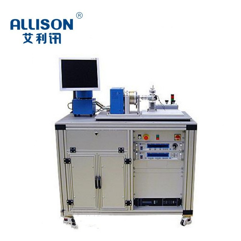
1.1 The motor testing equipment is customized based on the relevant technical parameters provided by the customer. Using a self-developed testing system with a brake as the loader; Perform motor torque testing using torque and speed sensors; The power transmitter is used for motor electrical parameter testing to complete voltage measurement, current measurement, speed measurement, power measurement, efficiency measurement, Hall phase signal acquisition and detection functions, and noise acquisition testing; Using digital temperature sensors for temperature measurement;
1.2 Design motor testing software according to user requirements, output motor testing reports, automatically generate QR codes after testing, and upload them to the internal traceability system (optional). The entire system is a comprehensive motor testing platform. Realize the recording and judgment of relevant parameters such as voltage, current, Hall signal, running time, running speed, temperature, and locked rotor overload function of the tested product during the testing process. Adopting our independently developed PLC electrical testing system. Perform programmable forward and reverse power supply testing on the tested products, and the relevant test data and Hall signals are automatically collected by PLC. And the control system automatically saves and exports USB data.
1.3 The system can capture transient torque, speed, three-phase voltage, current, power of servo motor input, system frequency voltage, current, power, DC voltage and current parameters.
2. The system can complete transient tests for servo motor no-load start-up, load start-up, and transient tests when changing from one load to another, recording fluctuations in parameters such as speed, torque, voltage, and current during the testing process.
3. The system automatically and continuously or manually loads the torque from 0 to the set value loading rate within a specified time, thereby completing the steady-state performance test of the servo motor/system at a certain speed, and drawing the steady-state performance curve M=f (U, I, Win, n, Wout, η).
4. The system completes the durability or temperature rise test of the servo system by providing a torque value adjusted by PID, allowing the servo motor to operate continuously for a long time at a constant torque.





 Online
 Tel
Tel Contact
 Home
Home